Die Springs
Die Springs are used as standardised compression springs for mechanical engineering, for example in presses and similar industrial applications, and comply with ISO and DIN standards.

Die Springs are used as standardised compression springs for mechanical engineering, for example in presses and similar industrial applications, and comply with ISO and DIN standards.
Are you interested in this product or do you need further information? Simply use our enquiry form - we will get back to you as soon as possible.
How would you like to submit your enquiry?
Choose the option that suits you best:
Online form: fill in and send directly in your browser. The form can also be saved as a PDF, printed out and completed by hand.
Compact print PDF: high-quality, printable PDF with form fields for printing.
Note:
So that you can enter the dimensions and characteristics of your spring correctly in the form, you will find an overview of the abbreviations used below.
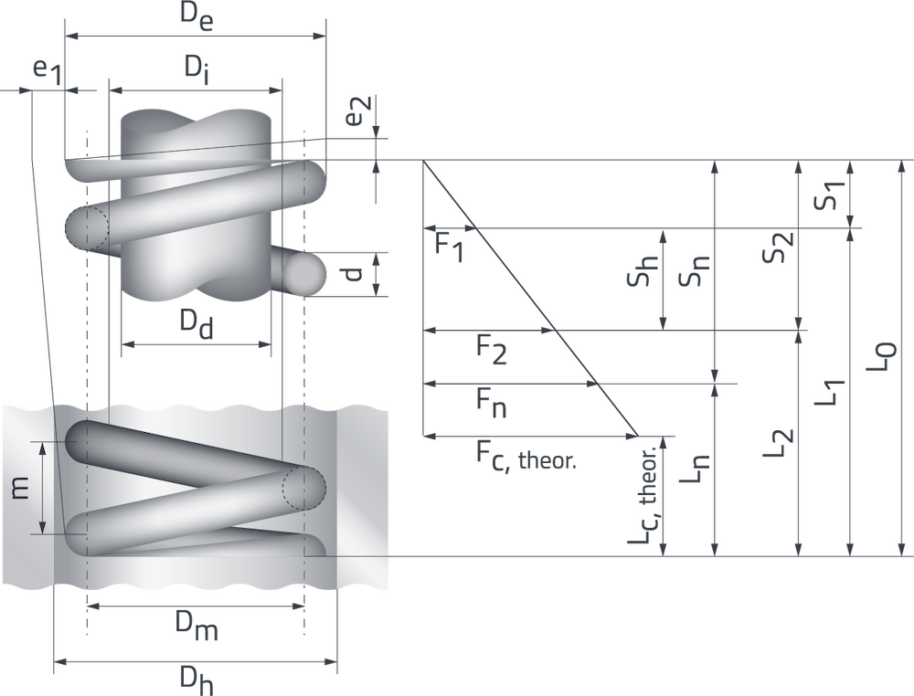
Technical drawing with dimensions
The required dimensions can be found here.
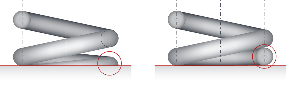
Possible shapes of the spring ends
Mould 1 (left): Ends laid out and ground flat
Mould 2 (right): Ends laid out and unfinished
| Sign | Unit | Naming |
|---|---|---|
| d | mm | Wire gauge |
| De | mm | Outer diameter |
| Dm | mm | Medium winding diameter |
| Di | mm | Inner diameter |
| Dd | mm | Guide arbour diameter |
| Dh | mm | Diameter of guide sleeve |
| L0 | mm | Spring length unloaded |
| L1 | mm | 1st approach length |
| L2 | mm | 2. approach length |
| Ln | mm | Smallest permissible approach length |
| Lc theor. | mm | Block length theor. |
| F | N | Spring force |
| F1 | N | Force at 1st approach length |
| F2 | N | Force at 2nd approach length |
| Fn | N | Maximum spring force |
| Fc theor. | N | theor. spring force to block length Lctheor. |
| e1 | mm | Deviation from the lateral line (skew) |
| e2 | mm | Deviation of the parallelism of the two contact surfaces |
| n | Effective number of turns | |
| nt | total number of turns | |
| m | mm | Gradient |
| M | g | Mass of the spring |
| R | N/mm | Spring rate |
| s | mm | Spring travel |
| sh | mm | Hub, commute |
| sn | mm | Spring travel to shortest approach length |
| sc | mm | Spring travel up to the theoretical block length |
| s1 | mm | Spring travel to 1st approach length |
| s2 | mm | Spring travel to 2nd approach length |
| Lk | mm | Buckling length |
| sk | mm | Spring travel up to buckling force |
| Fk | N | Buckling force |
| Sa | mm | Sum of the minimum clearances between the windings |
| fe | 1/s | Natural frequency of the spring |
| G | N/mm2 | Shear modulus |
| k | Voltage coefficient | |
| W | N/mm | Suspension work |
| w=D/d | Winding ratio | |
| v | Storage coefficient | |
| p | kg/dm3 | Density |
| τ | N/mm2 | Shear stress, without consideration of the wire curvature |
| τc | N/mm2 | Shear stress, assigned to the block length Lc |
| τk | N/mm2 | Corrected shear stress with consideration of the influence of the wire curvature |
| τn | N/mm2 | Shear stress, assigned to the spring force Fn |
| τzul | N/mm2 | Permissible shear stress |